

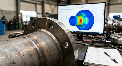
The solver finishes. On screen sits a field of stresses and displacements. That field does not answer the question the project actually asks: Does the structure pass code or not?
Between the solver output and that verdict lies a separate route. Physical quantities get converted into utilization factors, load combinations get cycled through, and a report gets assembled for certification.
The sections below map out the stages of that route and what it takes to carry a result through to a verdict without breaks between tools.
A Field of Results Is Not a Verdict
FEA outputs physics: stresses in megapascals, displacements in millimeters, forces in newtons. Code asks for something else. It wants a dimensionless utilization factor that has to stay at or below one. Translating one into the other is what verification actually is.
First, the result has to be judged fit for checking. The validity of the field depends on the mesh, the boundary conditions, and solution convergence. ASME BPVC VIII Div 2 Part 5 sets the threshold here: peak stress must not change by more than five percent between two successive mesh refinements. A field that has not converged is no basis for any code check. No amount of downstream arithmetic fixes that.
Translating Stress into Code Language
Raw solver stress cannot go straight against an allowable. This is where FEA reports stumble most often: an engineer takes the peak von Mises value and compares it to the allowable S, which is not how the code works.
ASME requires decomposing the stress field through the wall thickness. The membrane component Pm is the average across the section, P/A. The bending component Pb varies linearly through the thickness, Mc/I. The peak component is whatever remains on top. Each one goes against its own limit: Pm at or below S, Pm plus Pb at or below 1.5·S. Stress linearization came out of nuclear pressure vessel analysis in the 1970s and has been written into the code ever since.
Members translate differently. Here, Eurocode 3 (EN 1993-1-1) runs through section classification, slenderness, and buckling length, and only then combines axial force with bending in a single interaction check. AISC 360 reaches the same result through its H1-1a interaction equation. The output is again one number against a limit of one.
Fatigue adds another dimension. Here, the governing quantity is the stress range over the full cycle history, and a single peak value carries little weight. The solver field is recomputed into a hot spot stress, multiplied by a stress concentration factor, and checked against the appropriate S-N curve under Miner’s rule. For marine structures, DNV-RP-C203 governs this, and for steel detail categories under Eurocode, it is EN 1993-1-9. The same set of solver results passes through several different translations, depending on what is being checked: static strength, stability, or fatigue life.
Where the Process Loses Speed
Scale rules out manual review. After translation, every element has to be checked under every load combination and for every check type. On an offshore platform or a heavy lift, the combination count runs past three hundred, and the total number of utilization values on a large model climbs into the tens of thousands. Picking the governing cases by eye is not an option, so engineers fall back on envelopes or on hand-selecting the combinations they believe govern. The one that actually governs often sits among the combinations nobody opened.
Then the hand-offs between tools. Once a check moves into a spreadsheet, the data is frozen to a single moment. Any change to geometry or boundary conditions breaks the link to the model, and decisions get made on stale numbers. A spreadsheet exported to Excel reflects only the state the model was in at export time.
The report is exposed too. In certification, it carries the weight of a legal document. ASME lays out a thirteen-section structure for it:
- Executive Summary
- Design Basis
- Geometry
- Materials
- Load Matrix
- Model
- Mesh Validation
- Analysis Results
- Stress Linearization
- Plastic Collapse
- Fatigue
- Buckling
- Conclusions and Certification
Assembled by hand, screenshots go out of date, tables get rebuilt on every iteration, and one stress categorization error sends the document back for revision. Each rejection is a fresh review cycle, and a couple of those are enough to push the schedule out by weeks.
An End-to-End Route from Model to Report
The hand-offs between stages are what create the bottleneck. The formulas have nothing to do with it. Keep the whole path on a single analysis model, and the hand-offs disappear along with the breaks.
Structural verification software such as SDC Verifier carries the result from the stress field through to the utilization factor and the code clause, without exporting data outside. It starts with geometry recognition. The software reads the mesh back into engineering entities: a set of collinear elements is recognized as a single member, a shell field between stiffeners as a panel, a connection node as a fatigue check location. Buckling length is then measured over the whole member. At the level of a single finite element, that calculation means nothing. If the geometry is recognized wrong, everything downstream assigns the utilization factor to the wrong object.
The next stage is the combinations. Base loads are summed by linear superposition once the solution is done, with no second call to the solver, and an automatic scan finds, for each element, the combination that loads it hardest. There is no need to guess the governing scenario in advance. The report itself is tied to the model: a geometry edit triggers a recompute and a fresh version of the document, where each element shows its location, the critical load, the numbers substituted into the formula, and the verdict with its code reference.
It works in two modes. One as a standalone package with a built-in Nastran solver. The other is an extension for Ansys Mechanical, Femap, or Simcenter 3D, running on the same model that those environments already solve.
Where Continuity Pays Off
Verification is rarely a one-time pass. A factor above one means the element has to change, and a section edit is followed by a re-check. This is where a continuous process shows its value. When the link to the model holds, the cycle of check, resize, check again runs in minutes, where a manual report rebuild once costs weeks for the same edit. Engineering time shifts toward engineering decisions, away from filling in tables.
The Line Between Calculation and Judgment
Automation removes the arithmetic and the data transfer. Engineering judgment stays with the person. The software computes against the code and the edition it was given. The choice of standard, its current edition (EN 1993-1-9 was revised in 2025, DNV-RP-C203 was updated in October 2024), and the interpretation of boundary conditions remain a human call. Responsibility for the numerical result rests with the engineer. The vendor does not carry it.
This shift toward end-to-end processes has a workforce dimension as well. Deloitte estimates that engineering and construction will be short by roughly half a million workers by 2026. When routine cross-checking no longer takes hours, the same headcount closes more projects. And the traceability of every utilization factor back to its load combination and code clause speeds up independent review by a classification society.
The goal of verification does not move: carry the solver result through to a verdict that survives outside review, and back it with a document. An end-to-end process lowers the cost of that verdict in time and in errors, and leaves the methodology and the responsibility with the engineer.
 Cloud DMZ vs. Traditional Security Solutions: Which is Better?
 IntelliChief Intelligence ’19 User Conference
 5 Reasons Why You Should Choose Custom Tuck Boxes
 Elemica’s Gary Neights Wins Top 50 Tech Visionary Award
 Inmarsat takes another leap forward with ELERA, the global network for IoT, safety & mission critical connectivity
 Risks Associated with Choosing an Unlicensed Moneylender